I'm not sure where and how I first came upon multirotor radio controlled aircraft. In any case, I just new that is something for me. Initial research was a bit sobering, seeing what many commercial RC multicopter kits sell for. Sorry, I am not looking for a second car.
Thankfully, there are a number of open alternatives, and after some further research I was taken with the simplicity and effectiveness of AlexinParis' MultiWiiCopter project. It is based on an Arduino programmable micro controller and a MEMS gyroscope from a Wii Motion Plus. Simplistic, effective, and extensible. Added bonus: the flight control software is open source so your imagination is the limit.
The most popular designs are based on a quad rotor setup, usually built using aluminum tubing which is light, cheap, and easy to construct. A basic design guide can be found here. If money is no issue, CNC machined carbon frames like this one are available. If you have imagination, and access to your own CNC machine, then this or this may be something you want to look into.
I've decided to go with something slightly different, a frame based on 10mm EPP foam, sandwiched between layers of 1.5mm FR4 glass fibre. So far, I've not come across a similar approach. I'm hoping for light weight, sufficient crash resistance, and vibration dampening - while having some design freedom compared to the DIY look of aluminum tubing. Btw, I do have 2 meters of aluminum tubing as a backup. Just in case!
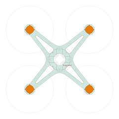
The design is based upon a set of Turnigy 2204-14T motors, each placed at the corner of a 20cm (8 inch) square. With 6x3 props, they should turn out approx 320g of max thrust per motor on a 3s Lipo battery. With an anticipated take-off weight of 450g, this provides a very decent thrust-to-weight ratio of 2.8:1. If that is not enough, 7x3.5 props on a 3s should deliver over 400g of thrust if needed. The closeness of the motors and overall size is perhaps not ideal stability wise, but I've made a conscious effort to keep it small without becoming bleading edge.
The heart of this design is a shield board designed by warthox which AlouetteIII has extended and commercialized. You can order it at http://www.multiwiicopter.com. Shipping from Australia was very quick, I received the board in a matter of a few days after placing my order.
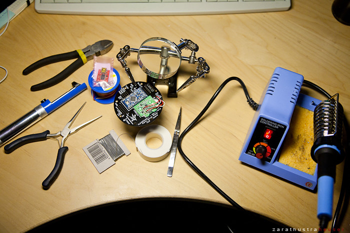
Today, I took delivery of the final parts to build the board, so I dusted off my rusty soldering skills and got going. It was really quite straight forward, in large part thanks to the following video which outlines how to connect the Wii Motion Plus (WMP) board. I went with an original WMP instead of a china knock off to keep my first build simple: http://www.multiwiicopter.com/pages/videos
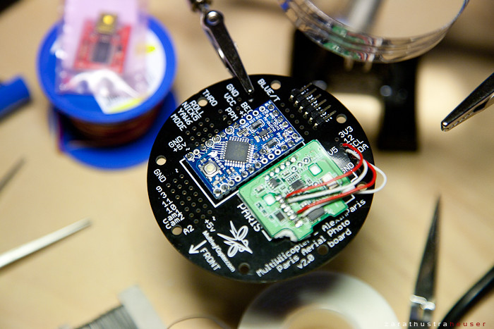
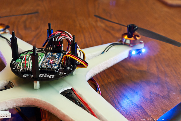
Here the almost finished board, getting ready for the first test:
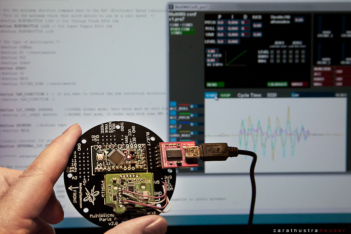
After downloading the Arduino development platform and the latest MultiWiiCopter release, flashing the Arduino board was a breeze, and the GUI started showing the gyroscope outputs from the WMP board.
Next, I took delivery of a Bosch BMA020 accelerometer (or ACC) breakout board, which Norbert a.k.a. Kinderkram from the RCGroups forum was kind enough to send my way. While the original MultiWiiCopter design uses the accelerometer from a Nintendo Nunchuk controler, the BMA020 is a smaller, cheaper, better performing alternative.
By the way, If you are holding back on the BMA020 because it is advertised as an assembly kit - assembly is limited to soldering the external connectors to it. The board itself is pre-soldered, no micro SMD voodoo required.
At 6 Euros a piece it's really a no brainer, except for the exorbitant shipping fees that the distributer ELV charges - in particular for shipments outside of Germany. Norbert is kind enough to place a bulk order with ELV every few weeks and then sends out the boards at cost to whomever is interested. Be thankful if he continues to offer this service, and considerate if at some point he decides he's had enough.
The ACC provides support for auto-level mode, removing the need for constant corrections from the pilot to keep the aircraft level. This is especially helpful for aerial photography and FPV flying - which I am both interested in eventually. You have the option to turn the auto-level mode on or off from your transmitter.
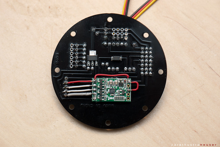
Attaching the BMA020 was fairly straight forward. As there was little room left on the front of the board, I decided to mount it on the back using a single layer of foam tape. To connect the board, you need to wire it to the I2C bus of the Arduino board - in parallel to the WMP. A wiring diagram is provided here, and the general orientation of the board here.
Below you can see the bottom of my Arduino shield board with the ACC connected to the I2C bus. The BMA020 board is 5V friendly and has internal pull-up resistors, so no need for any extra parts:
To enable the ACC, you need to comment out the following line from the Arduino sketch:
Also, since I mounted the board to the bottom, I needed to invert the Y and Z axis as follows (note the placement of the negative signs):
ORIGINAL:
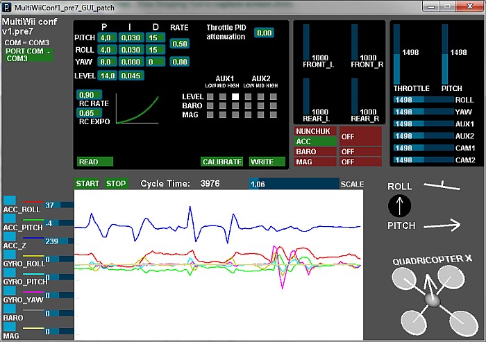
After re-compiling the sketch, and flashing it to the Arduino, I was able to see the ACC values and the spatial orientation of the board show up in the configuration GUI. Note that you need to level the board and press the calibrate button before you see accurate values:
Finally, after waiting what seemed like ages (I'm not the most patient person) my hardware arrived via Singapore. After paying the required ransom, I was able to pick up my package at customs. Following a final verification of the mounting hole distance on the Turnigy 2204-14T motors (31mm), I cut the top and bottom part of the frame from a sheet of 1.5mm FR4/G10 fiber glass. A jig saw and a Dremel were quite helpful in the process.
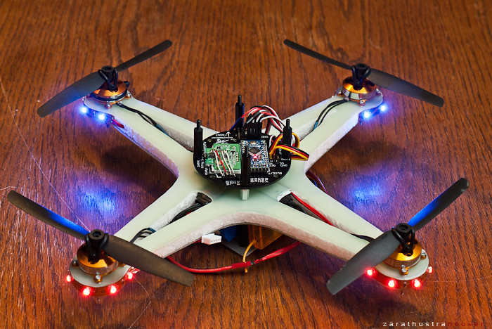
The pieces were then used to sandwich a 10mm EPP foam board, with embedded 10mm M3 hex standoff spacers at the mounting points for the controller board. This allows to attach the MultiWii board on top and a battery and Rx compartment at the bottom. The ESC motor control boards are embedded in the frame. The final design can be seen below, without the top plate which was off to re-program the micro controller with the newest software version:
Main Components:
Motors: Turnigy 2204-14T
ESCs: Hobbyking SS Series 8-10A
Lipo: 1000mAh 3S 20C
Props: GWS Style 6x3
Rx: OrangeRx DSM2
Total weight ready to fly: 410grams (incl battery)
Thrust to weight ratio: approx 2.8:1
Sound: An angry bee hive on steroids
Below a short video to further illustrate the results. While the build went smooth, I think I will need to practice flying this thing :-)

Flash player v9 or newer required.
Thankfully, there are a number of open alternatives, and after some further research I was taken with the simplicity and effectiveness of AlexinParis' MultiWiiCopter project. It is based on an Arduino programmable micro controller and a MEMS gyroscope from a Wii Motion Plus. Simplistic, effective, and extensible. Added bonus: the flight control software is open source so your imagination is the limit.
The most popular designs are based on a quad rotor setup, usually built using aluminum tubing which is light, cheap, and easy to construct. A basic design guide can be found here. If money is no issue, CNC machined carbon frames like this one are available. If you have imagination, and access to your own CNC machine, then this or this may be something you want to look into.
I've decided to go with something slightly different, a frame based on 10mm EPP foam, sandwiched between layers of 1.5mm FR4 glass fibre. So far, I've not come across a similar approach. I'm hoping for light weight, sufficient crash resistance, and vibration dampening - while having some design freedom compared to the DIY look of aluminum tubing. Btw, I do have 2 meters of aluminum tubing as a backup. Just in case!

The design is based upon a set of Turnigy 2204-14T motors, each placed at the corner of a 20cm (8 inch) square. With 6x3 props, they should turn out approx 320g of max thrust per motor on a 3s Lipo battery. With an anticipated take-off weight of 450g, this provides a very decent thrust-to-weight ratio of 2.8:1. If that is not enough, 7x3.5 props on a 3s should deliver over 400g of thrust if needed. The closeness of the motors and overall size is perhaps not ideal stability wise, but I've made a conscious effort to keep it small without becoming bleading edge.
The heart of this design is a shield board designed by warthox which AlouetteIII has extended and commercialized. You can order it at http://www.multiwiicopter.com. Shipping from Australia was very quick, I received the board in a matter of a few days after placing my order.
Today, I took delivery of the final parts to build the board, so I dusted off my rusty soldering skills and got going. It was really quite straight forward, in large part thanks to the following video which outlines how to connect the Wii Motion Plus (WMP) board. I went with an original WMP instead of a china knock off to keep my first build simple: http://www.multiwiicopter.com/pages/videos
Here the almost finished board, getting ready for the first test:
After downloading the Arduino development platform and the latest MultiWiiCopter release, flashing the Arduino board was a breeze, and the GUI started showing the gyroscope outputs from the WMP board.
Next, I took delivery of a Bosch BMA020 accelerometer (or ACC) breakout board, which Norbert a.k.a. Kinderkram from the RCGroups forum was kind enough to send my way. While the original MultiWiiCopter design uses the accelerometer from a Nintendo Nunchuk controler, the BMA020 is a smaller, cheaper, better performing alternative.
By the way, If you are holding back on the BMA020 because it is advertised as an assembly kit - assembly is limited to soldering the external connectors to it. The board itself is pre-soldered, no micro SMD voodoo required.
At 6 Euros a piece it's really a no brainer, except for the exorbitant shipping fees that the distributer ELV charges - in particular for shipments outside of Germany. Norbert is kind enough to place a bulk order with ELV every few weeks and then sends out the boards at cost to whomever is interested. Be thankful if he continues to offer this service, and considerate if at some point he decides he's had enough.
The ACC provides support for auto-level mode, removing the need for constant corrections from the pilot to keep the aircraft level. This is especially helpful for aerial photography and FPV flying - which I am both interested in eventually. You have the option to turn the auto-level mode on or off from your transmitter.
Attaching the BMA020 was fairly straight forward. As there was little room left on the front of the board, I decided to mount it on the back using a single layer of foam tape. To connect the board, you need to wire it to the I2C bus of the Arduino board - in parallel to the WMP. A wiring diagram is provided here, and the general orientation of the board here.
Below you can see the bottom of my Arduino shield board with the ACC connected to the I2C bus. The BMA020 board is 5V friendly and has internal pull-up resistors, so no need for any extra parts:
To enable the ACC, you need to comment out the following line from the Arduino sketch:
/* I2C accelerometer */
//#define ADXL345
#define BMA020
//#define BMA180
Also, since I mounted the board to the bottom, I needed to invert the Y and Z axis as follows (note the placement of the negative signs):
ORIGINAL:
accADC[PITCH] =  (((rawADC_BMA020[3])<<8) | ((rawADC_BMA020[2]>>1)<<1))/64;
accADC[YAW]   = -(((rawADC_BMA020[5])<<8) | ((rawADC_BMA020[4]>>1)<<1))/64;
MODIFIED: accADC[PITCH] = -(((rawADC_BMA020[3])<<8) | ((rawADC_BMA020[2]>>1)<<1))/64;
accADC[YAW] = (((rawADC_BMA020[5])<<8) | ((rawADC_BMA020[4]>>1)<<1))/64;
After re-compiling the sketch, and flashing it to the Arduino, I was able to see the ACC values and the spatial orientation of the board show up in the configuration GUI. Note that you need to level the board and press the calibrate button before you see accurate values:
Finally, after waiting what seemed like ages (I'm not the most patient person) my hardware arrived via Singapore. After paying the required ransom, I was able to pick up my package at customs. Following a final verification of the mounting hole distance on the Turnigy 2204-14T motors (31mm), I cut the top and bottom part of the frame from a sheet of 1.5mm FR4/G10 fiber glass. A jig saw and a Dremel were quite helpful in the process.
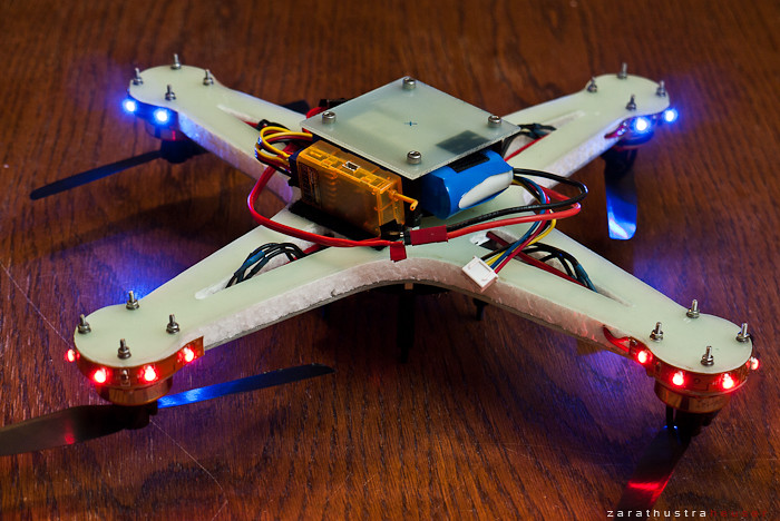
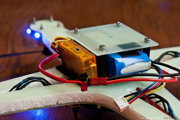
The pieces were then used to sandwich a 10mm EPP foam board, with embedded 10mm M3 hex standoff spacers at the mounting points for the controller board. This allows to attach the MultiWii board on top and a battery and Rx compartment at the bottom. The ESC motor control boards are embedded in the frame. The final design can be seen below, without the top plate which was off to re-program the micro controller with the newest software version:
Main Components:
Motors: Turnigy 2204-14T
ESCs: Hobbyking SS Series 8-10A
Lipo: 1000mAh 3S 20C
Props: GWS Style 6x3
Rx: OrangeRx DSM2
Total weight ready to fly: 410grams (incl battery)
Thrust to weight ratio: approx 2.8:1
Sound: An angry bee hive on steroids
Below a short video to further illustrate the results. While the build went smooth, I think I will need to practice flying this thing :-)
Flash player v9 or newer required.

No comments:
Post a Comment